TL;DR
Project Description and Background
During the academic year 2011-2012 I worked as a teaching assistant in a machine shop on Purdue campus. We had lots of cool machines, like CNC mills, CNC lathes, horizontal band saw, waterjet, and others. This project focuses on the CNC mills. In order to machine parts on the mills, we need to hold them, and this is typically accomplished using a vice assembly like the one shown below.
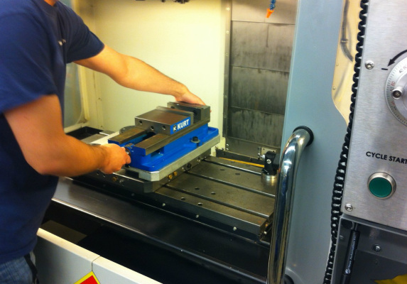
One of the vice assemblies we use in our mills. Not only are they heavy, with virtually no good spot to grip them, they are also a couple feet into the machine.
The vice assembly sits on what is called a chuck plate (the dark grey object sitting on top of the machining table, NOT the light grey object right below the vice assembly, further down), so that you could lift it in and out of the machine, and get the same positioning and orientation every time to within a couple of microns (1 micron = 0.00003 inches).
The problem comes with the lifting in and out of the machine. The vice assemblies are heavy, around 50 lbs. What's worse is they have no grips, and they sit a couple feet inside the mill, which makes lifting them a huge strain on the person lifting. In order to simplify this process, it was decided that we would get an engine hoist.
The problem comes with the lifting in and out of the machine. The vice assemblies are heavy, around 50 lbs. What's worse is they have no grips, and they sit a couple feet inside the mill, which makes lifting them a huge strain on the person lifting. In order to simplify this process, it was decided that we would get an engine hoist.
Design Problem
The problem we ran into with using an engine hoist to lift the vice assemblies is that the CNC mills sit very low to the floor, leaving only 3.5" of clearance between the machine and the floor. Most engine hoists are designed to go under a car, which, of course, has a much larger clearance. As such, the engine hoist needed modifications in order to be able to fit under the machines.
Concept
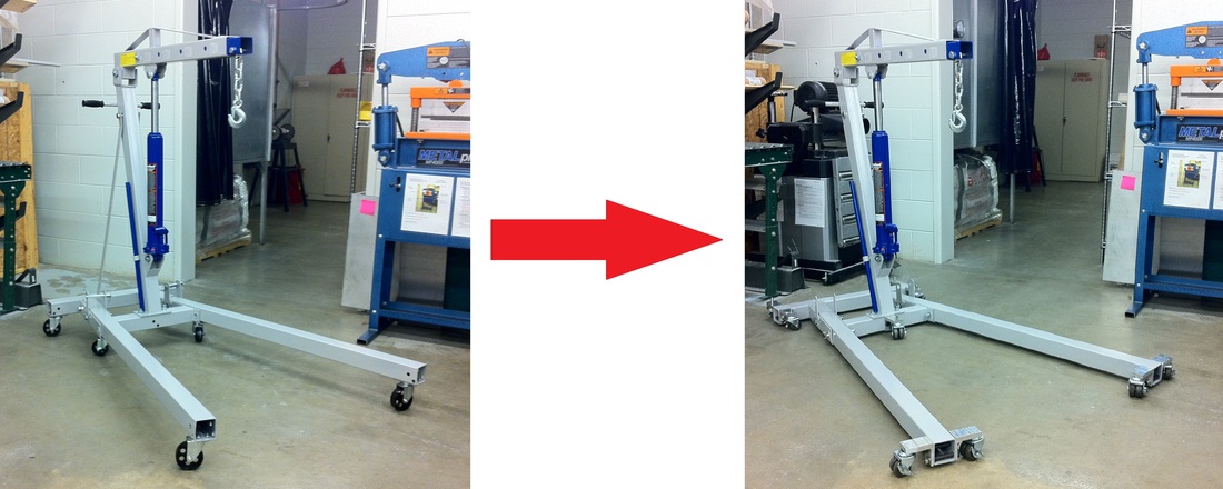
Following is an image of the engine hoist we purchased:
The engine hoist we purchased to help with the vice assemblies, put together in its original form. In this configuration, it is too tall to fit under the machines.
The legs extend outwards in order to support the object being lifted. As you can see, the hoist rides on top of caster wheels. The caster wheels themselves are 3.5" in diameter or more (the ones in the middle are different). But the tubing is only 2.8" in height (the hoist was specifically purchased for this reason). So the idea was to get new casters of a smaller diameter, and make custom side-mounts for them. Following is a CAD image of what the mounts would look like:
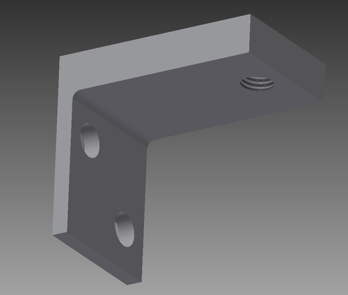
Two of these would go onto either side of the square tubing on the hoist in place of where the original casters were. The caster with its threaded stem would fit in the threaded hole seen in the model.
The single hole you see on top would be threaded in order to accept threaded stem casters. Then two of these mounts would go on either side of the steel tubing in place of the original casters, and two 1/2" bolts would go through the mount, through the tubing, and through the mount on the other side, being secured on said other side with a nut and lock washer.
Analysis
But would this design work? The main question is how strong are these side-mounts going to be? They don't have to be too strong in order to allow the hoist to lift the vice assemblies, but the hoist was also intended to lift a large 5-600 lb trunnion that fits into the machines and enables 5-axis cutting capabilities. And who knows, perhaps at some point down the line it will be needed to lift something very heavy. In order to perform this analysis, there needed to be a design limit for the mounts. Since the new 2.5" casters we purchased were rated to 225 lbs each, that made sense as a design load. Given this load, a structural analysis was performed in Autodesk Inventor, the results of which are seen below.

Stress is concentrated on the inside radius, which one might expect. However, the maximum stress is far less than the yield stress of the aluminum used.
The yield strength of aluminum 6061, a typical alloy, can range from 16-40 ksi, although the aluminum used to make the mount, a temper from Alcoa called 7055-T77511 is rated to 89 ksi, according to Alcoa. Although this seemed unusually high, the stresses encountered by this part are below the typical yield stress of aluminum, and therefore caused no concern.
Manufacturing
In order to save time and effort, the side-mounts were machined out of a double I-beam from the shop's scrap pile. The sections you see in red were removed either with a band saw or on the mill, and further work was done on the rest of the piece (in green) on the mill.
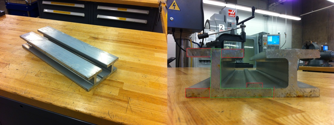
This double I-beam we had in the scrapyard made manufacturing of the side-mounts very easy. On the right, the profile view shows material that had to be removed in order as well as the general shape of the side-mount in green (it's upside-down).
A somewhat more challenging aspect of the construction was drilling the engine hoist itself, since it needed holes to accommodate the 1/2" bolt mentioned previously. The legs were fairly straightforward to drill. They were simply set up in the drill press like any other part, with a riser used to hold up the elongated end. An extra long 33/64ths drill bit was used, which required removing the spindle chuck (after drilling a pilot hole with a center drill) and inserting an adapter for the extra long bit.
The holes were spotted by using a completed side-mount, clamping it onto the leg in the place where it would eventually be attached, and using a transfer punch to mark the location on the leg for drilling.
The holes were spotted by using a completed side-mount, clamping it onto the leg in the place where it would eventually be attached, and using a transfer punch to mark the location on the leg for drilling.
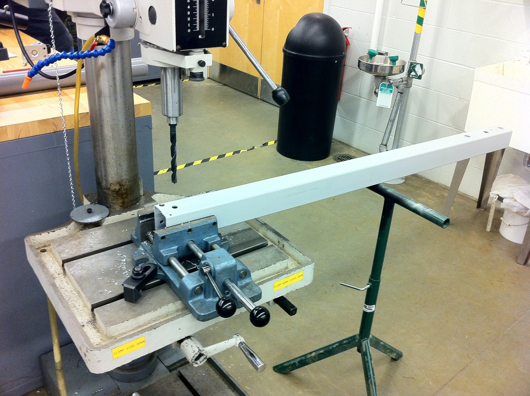
Drilling the long legs of the hoist on the drill press. These holes are for the bolts that secure the side-mounts to the hoist itself.
The base was much more interesting, and stretched the physical envelope of the drill press to the limit. The table had to be lowered all the way down, and with the 33/64ths drill bit in the machine, the clearance between the bottom of the drill bit and the part was less than 1"
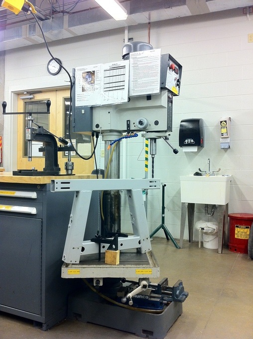
The base of the engine hoist on the drill press. The side facing the camera is the bottom side. Notice the drill bit roughly in the middle of the picture and how close it is to the part!
There were also a lot of vibrations from drilling in such an awkward position. In order to suppress them, one person physically held on to the part while another person drilled the hole.
Final assembly
With all the side mounts machined and all the engine hoist pieces drilled, the final assembly was straightforward enough:
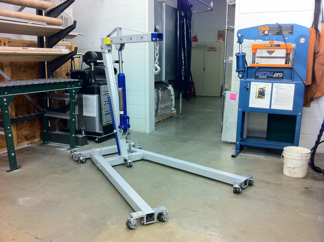
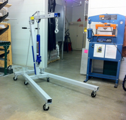
Fully assembled hoist!
